Volume flow, flow speed and other technical terms in ventilation
How much air can a fan transport, how fast with the transport be and what pressure is needed to do so are important aspects for compatibility of a ventilation appliance and your building. Laymen often do not know what exactly the technical terms mean, so we will try our best to explain the terms volume flow, operating point and flow velocity.
Reading time: 13 min. or skip to the summary
Contents:
- Volume flow of ventilation appliances
- Example for airflow rate
- What are standard and minimum design flow rate?
- Not all pipes are the same
- What is the fan characteristic curve?
- Flow speed
- Supply and exhaust air
- Summary
Volume flow of ventilation appliances
The volume flow (meaning the quantity, the volume) and velocity of fluid or gas in a determined diameter (e.g. a pipe) is calculated in the field of science and technology, particularly when it comes to thermodynamics. For example, the blood flow in our veins, the transportation of oil, coolant and even supply air in ventilation systems all require these measurements. The word volume flow is synonymous with the terms flow rate, delivery rate and airflow.
The volume flow describes the quantity that is transported in a specific area within a certain timeframe. The value is usually stated in cubic metres per hour.
Naturally, the flow changes in accordance with the fan speed (revolutions per minute) and depends on the changing air pressure (e.g. in clogged exhaust shafts) as well as change in temperature (cool outdoor air has less mass than warm indoor air).
Example for airflow rate
The type of the room and how you are using it is also an important factor for the selection of a device. A schoolroom must be ventilated differently than a painter’s shop with hazardous gas. Extractor fans are mainly used in damp rooms and work places with odours to support efficient air change. Our item descriptions always state the value of the fan’s airflow in m3/h. However what does that measurement mean for you?
Empirical values have been collected for various rooms and intended use of the room. These values are reflected in the recommended air change rate per hour for the identification of the quantity of air.
We shall take a bathroom without any windows in a 1-person household. The coefficient for the air change per hour is 5. Assuming a room size of 15m3 this results in an air volume of 75m3 that is required per hour.
Calculation: 5 x 15 = 75
A bathroom fan with the following specifications should be considered for the room.
- Revolutions per minute (RPM): 2400
- Airflow rate (m3/h): 85
What are standard and minimum design flow rate?
The volume of gas depends heavily on temperature and pressure. If ambient air is heated by a heating unit, it loses density. That means the individual air molecules now have a greater distance between each other, their total dimension (the volume) increases. In order to provide a fair and reliable basis for comparison, the volume flow is determined by the single manufacturers in laboratories under standardised conditions. That is why it is also called manufacturer’s design flow rate. The flow rated stated by brands therefore means normal, standardised conditions with normal temperature and pressure without any extreme weather changes or other pollution such as dust.
Ventilation appliances that are installed in ducts and ventilation shafts the flow rate value is one of the decisive factors for reviewing the efficiency of the device. Ceiling fans that are hanging free and unobstructed in the room are also tested for airflow rates. However, in this case it is not the airflow in a limited pipe that has been measured, but rather the air circulation in the room. The more pressure a fan is able to build up with a powerful motor and perfectly design blades or impellers, the more suitable it is for the purpose of air change. Apart from the airflow rate, other values such as energy consumption and operational noise are important figures too.
Not all pipes are the same

Think of your childhood days. Did you ever blow a dandelion? The harder you blow on the head of the flower, the more and faster the individual strands flow away. If are are not blowing hard, there is little to no movement at all.
It is similar with air that is pressed into or sucked out of a ventilation shaft by a ventilator. The flow force in straight pipes with a round cross-section has the best measurements. However, even despite optimum conditions air is flowing better in the centre of the pipe, on the side of the pipe the velocity slows down due to friction force of the walls of the pipe. Bent and square shafts experience even more resistance. Curved pipes or pipes that gradually transition to a bigger or smaller diameter measurably impact the current profile. Furhtermore, long ducts and obstacles such as filter flaps increase friction as well.
Pipes impact the airflow with:
Even the most powerful fans will lose pressure when encountering an excessive amount of disturbing factors. That is why frequent checking and perhaps cleaning of the vents is required. If possible, the entire system can be upgraded. Factors that cannot be altered due to construction are determined by the person or company that installed your entire system and shown in the system’s characteristic curve. With these values at hand the selection of a suitable fan is much easier.
What is the fan characteristic curve?
Now we are moving on to technics. The characteristic curve is important for the planner or ventilation engineer. We will give you a rough outline of the topic so that you have a better understanding of what the images and curves in our item descriptions actually mean. We are mostly using these graphs for our window or wall-mounted fan ranges.
Before selecting a fan for the ventilation system, the following steps must be taken:

- Determine volume flow (see calculation for airflow rate)
- Collect information about piping system, resistance, pressure loss in the system’s characteristic curve
- The fan’s characterstic curve shows the correlation of volume flow and increase in pressure of the tested device. It is determined by the manufacturer and published in a spec sheet. However, seeing that the values have been tested under ideal environmental conditions with unobstructed air intake and exhaust, the values you are measuring on the device in your own system can differ from the official data.
The fan characteristic curve varies due to the construction of the fan:
Axial-flow fans (conventional desk and ceiling fans) have the best feed rate with the lowest friction resistance. Often they are not powerful enough to build up high pressure to overcome any obstacles such as cover flaps etc. However, this is not a general statement since there are also axial-flow fans with an outstanding airflow rate for application in industrial facilities.
Centrifugal fans (industrial plants, installation in pipes and ducts, central ventilation system) on the other hand generate a high amount of pressure and overcome high resistance thanks to special impellers that are similar to a paddle wheel.
The centrifugal Quadro Micro wall fan from the CasaFan range is a good example. The image shows how the four different models of the Quadro Micro series react to different conditions. The Micro 80 model (yellow curve) generates a maximum pressure of 265 Pa and achieves a maximum airflow rate of 85m3/h.
Now the curves from the system and the fan are compared with each other. The point where both graphs cross is called the operating point / working point of the fan. This point is where the additional pressure generated by the fan balances out the pressure loss resulting from the piping system. This is the maximum airflow rate this system can reach. In a different system these values are most likely different as you can see in the following example:
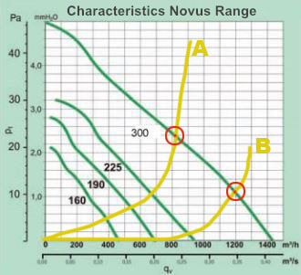
Take a look at the Novus window fan range. On the side you see an image with the characteristic curve of the model CATA LHV 300 (green colour). This value is stated by the manufacturer. The yellow markings reflect characteristics of the fictitious buildings A and B that were measured by a ventilation expert. Now, both piping systems are laid in a different way in each building, that is why both curves are different. Building A shows a higher flow resistance, perhaps due to outdated ventilation shafts.
The operating points with model CATA LHV 300 are marked in red. The fan that reaches an airflow of up to 1450m³/h according to the manufacturer’s normed testing under ideal conditions will only achieve 800m³/h inside the ventilation system of building A. In building B the same fan operates more efficiently with 1200m³/h.
When comparing different fan models, the choice will be the device that reaches the best airflow rate in the specified ducting system with all its turns and obstacles. The best result of the operating point is not the only decisive factor though, the power consumption should also be considered when looking for a suitable appliance. You can see how buying a fan is a complex matter that often requires a specialist.
Flow speed
If your ventilation plant has already been installed and you want to make sure it works efficiently, you can find air speed indicators at relatively cheap prices online. These anemometers determine the volume flow and air velocity on the air intake and air outlet of the ducts. The device uses light sensors or measures the movement of the blade wheels. The unit is held directly to the opening of the duct or the flowing air is lead to the measuring device with the help of a funnel. Laser technology allows measurement without touching the airflow so that any inaccuracies caused by an altered flow resistance are eliminated. Modern anemometers allow you to review results immediately on-site, measurements are shown on the display of the device. The transported air should neither be too slow nor too fast, the latter causes unpleasant draught. Air with a high speed makes residents feel cold and can lead to tense muscles.
Supply and exhaust air
Sufficient pressure build-up is particularly important for fans that are implemented in extensive shafts. After all, extracted air should not simply lose momentum halfway and simply flow back into the building. For that reason (central) ventilation systems use powerful extractor fans. In order to use such an extractor fan, the room must be provided with the same amount of fresh air supply as the amount of extracted air. The air stream is not only generated by connected rooms. Natural ventilation or other ventilation appliances provide the supply air. Air also infiltrates the system from outdoors by entering through openings, influencing the air velocity and temperature.
There are different ways to provide the necessary supply air for your room or even the entire building. Check out our guide about "air supply" for more information about this topic.
Summary
The volume flow created by a ventilation appliance’s pressure build up (particularly in wall-mounted and inline fans) needs to be considered in accordance with the inner diameter of the pipe and the provided flow speed. Not all pipes lead the same amount of air, meaning the best possible volume flow provided by the manufacturer does not equal the real flow achieved with your ducting system. That is why it is important to compare the characteristic curve of the model with the characteristic curve of your system. The system, in other words pipes in the building can obstruct the airflow with flow resistances such as bent pipes. The operating point is where the characteristic curves of the appliance and the system cross, the value describes the maximum airflow rate possible with the system. The fan most suitable with the system is chosen by considering not only the flow rate but also power consumption to ensure maximum harmoniousness with the existing system. The volume flow does not only depend on the technical specifications of the fan but also from the climate and piping system in situ. The selection of the right device is a complex matter, so we recommend consulting a professional.
Image sources:
Product pictures © creoven.de
Pipe © Kara - fotolia.com